- Español
- Português
- русский
- Français
- 日本語
- Deutsch
- tiếng Việt
- Italiano
- Nederlands
- ภาษาไทย
- Polski
- 한국어
- Svenska
- magyar
- Malay
- বাংলা ভাষার
- Dansk
- Suomi
- हिन्दी
- Pilipino
- Türkçe
- Gaeilge
- العربية
- Indonesia
- Norsk
- تمل
- český
- ελληνικά
- український
- Javanese
- فارسی
- தமிழ்
- తెలుగు
- नेपाली
- Burmese
- български
- ລາວ
- Latine
- Қазақша
- Euskal
- Azərbaycan
- Slovenský jazyk
- Македонски
- Lietuvos
- Eesti Keel
- Română
- Slovenski
- मराठी
- Srpski језик


Time Delay Starting 75C 1200OHM MZ31 PTC Thermistor Resistance For Lighting
MZ31 series of PTC Thermistor are applicable to various types of fluorescent lamp, electronic ballast and electronic energy-saving lamp. The PTC can be connected across the lamp resonator without changing the circuits.
Send Inquiry
Product Description
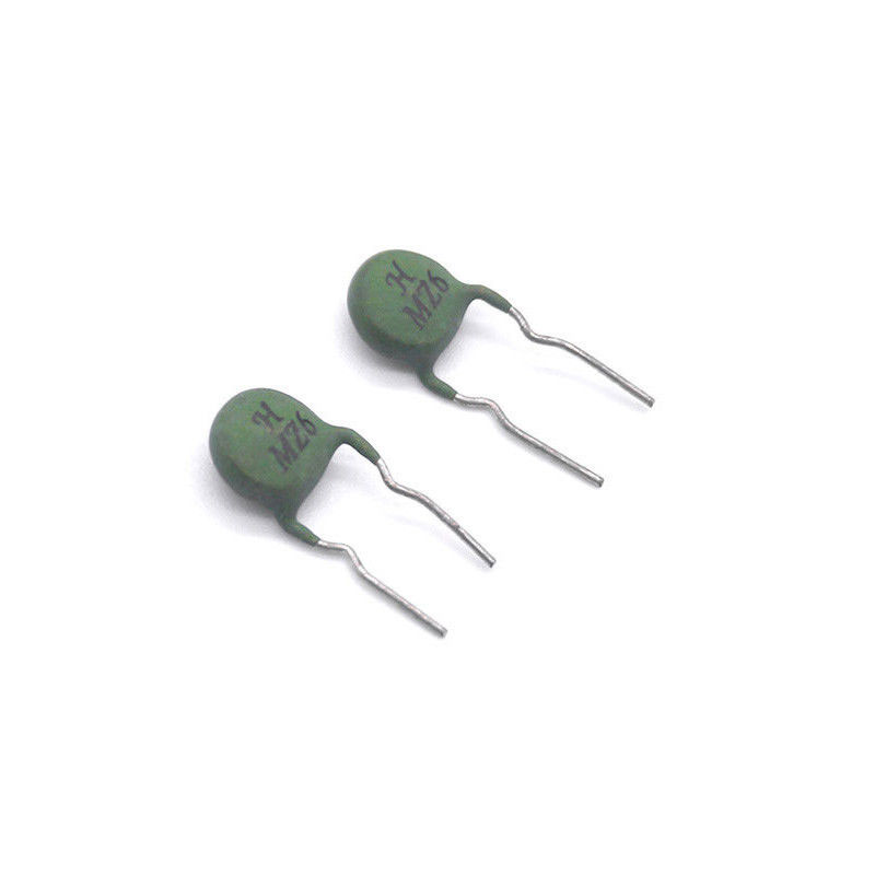
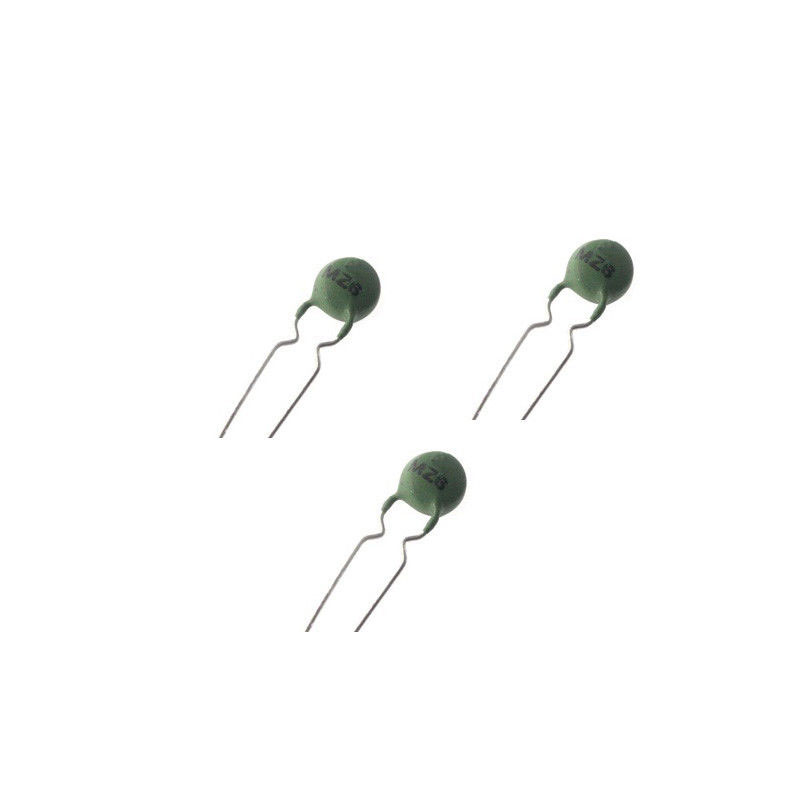
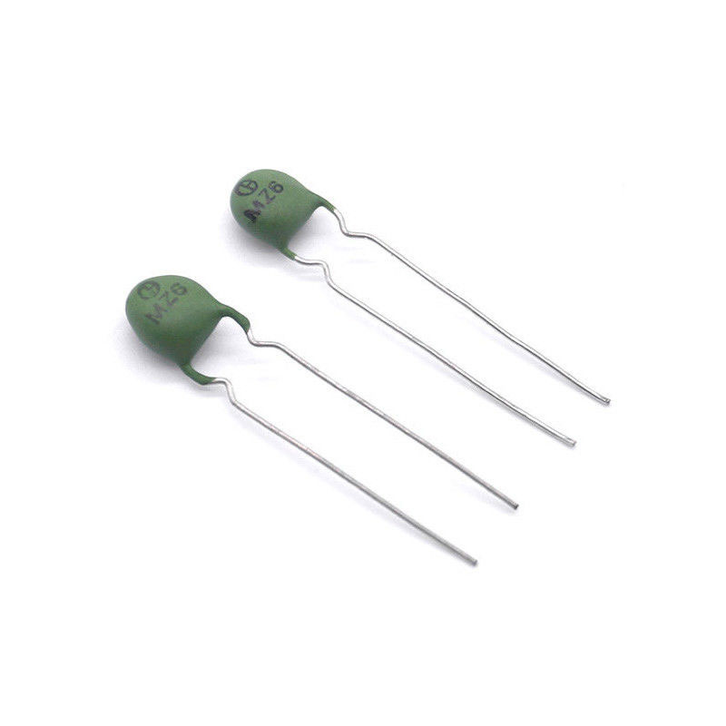
I Description Of The Time Delay Starting MZ31 PTC Thermistor MZ6
MZ31 series of PTC Thermistor are applicable to various types of fluorescent lamp, electronic ballast and electronic energy-saving lamp. The PTC can be connected across the lamp resonator without changing the circuits. It can change hard start of the ballast and electronic energy-saving lamp to preheated start and the preheating time of the filament can come up to 0.4-2 seconds, which will extend the service life of the fluorescent tube by over 3 times.
These directly heated ceramic-based thermistors have a positive temperature coefficient and are primarily intended for overload protection. They consist of a ceramic pellet soldered between two tinned CCS wires and coated with a UL 94 V-0 high temperature hard silicone lacquer.
The application of the PTC thermistor to achieve preheated start is as follows: Immediately after power is switched on, Rt is in normal temperature state and its resistance is far lower than the C2 resistance.
The current through C1 and Rt forms a return circuit to preheat the filament. After about 0.4-2 seconds, Rt joule heat temperature exceeds Curie point Tsw and skips into high resistance state of far higher than C2 resistance. The current passes through C1 and C2 to form a return circuit, which causes L resonance and produces high voltage to light the fluorescent tube.
• Small size
• High voltage (800 ~ 1000VAC more)
• Long life (more than 10,000 power switch)
• Power dissipation is low
• Wide range of trip and non-trip currents: From 11 mA up to 800 mA
• Small ratio between trip and non-trip currents (It/Int = 1.5 at 25 °C)
• High maximum inrush current (up to 5.5 A)
• Leaded parts withstand mechanical stresses and vibration
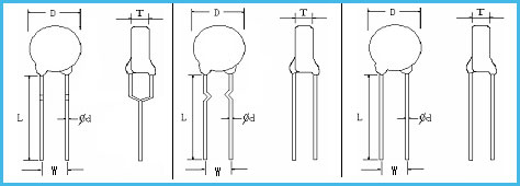
| Number | Name | Technical Requirements | Leads |
| D | Diameter | 6.0max |
□ Straight
□ Axis Formed
■ In-Forming |
| T | Thickness | 4.5max | |
| L | Lead Length | Min20 | |
| W | Distance between fuses | 5.0±0.5 | |
| d | Diameter of lead | 0.5±0.05 |
| Coating | Material | Color |
|
□ No coating ■ Coating |
□ PF resin ■ Silicon
|
■ Yellow ■ Green
|
| Number | Items | Technical Requirements | Test Conditions |
| 3-1 |
Resistant for Zero Rated Power |
800-1200Ω |
Atmosphere Temperature:25±2℃ Accuracy of the Test:±0.5% |
| 3-2 |
Over Voltage Withstanding |
≥800V ΔR/Rn≤20% No visual damage
|
Starting Current:≥200mA, Starting Voltage:220VAC,hold on for 7s,and then change to high voltage800VAC,for 6s.the is shown as follows: Stay under the conditions of regular temperature and humidity for 4-5 hours, and then check the Rn again. |
| 3-3 |
Over Current withstanding
|
≥500mA ΔR/Rn≤20% No visual damage |
Starting Current:≥200mA,Voltage 220VAC, switch on the circuit for 1 minute after every 5minutes, switch-off, and repeat this operation for 20 times. Put it under the conditions of regular temperature and humidity for 4-5 hours and then check the Rn again |
| 3-5 | Curie Temperature | 75℃ | Check the temperature at 2 times Rn. |
| Item |
MAX. VOLTAGE (V) |
CURRENT WHEN DON’T OPRATE AT 60℃(mA) | poses current when at -10 ℃ (mA) | maximum current(A) | Resistance when 25 ℃ (ohm) | Curie point (℃) | Ontology diameter (Dmax)(mm) | thickness (Tmax)(mm) | lead spacing (W)(mm) | Terminal diameter (phi d)(mm) |
| MZ6B06D120C180RM125V | 125 | 30 | 75 | 0.3 | 180 ±20% | 120 | 6.0 | 5.0 | 5.0 | 0.6 |
| MZ8B08D120C75RM125V | 125 | 65 | 165 | 0.3 | 75 ±20% | 120 | 8.0 | 6.0 | 5.0 | 0.6 |
| MZ8B10D120C47RM125V | 125 | 90 | 230 | 0.5 | 47 ±20% | 120 | 10.0 | 5.5 | 5.0 | 0.6 |
| MZ8B10D120C22RM125V | 125 | 135 | 340 | 0.8 | 22 ±20% | 120 | 10.0 | 5.5 | 5.0 | 0.6 |
| MZ8B13D120C15RM125V | 125 | 175 | 440 | 1.0 | 15 ±20% | 120 | 13.0 | 5.5 | 5.0 | 0.6 |
| MZ8B15D120C10RM125V | 125 | 220 | 550 | 1.2 | 10 ±20% | 120 | 15.0 | 5.5 | 5.0 | 0.6 |
| MZ8B17D120C6R8M125V | 125 | 300 | 750 | 1.4 | 6.8 ±20% | 120 | 17.0 | 5.5 | 5.0 | 0.6 |
| MZ8B17D120C4R7M125V | 125 | 360 | 900 | 1.7 | 4.7 ±20% | 120 | 17.0 | 5.5 | 5.0 | 0.6 |
| MZ8B17D120C3R3M125V | 125 | 420 | 1050 | 2.0 | 3.3 ±20% | 120 | 17.0 | 5.5 | 5.0 | 0.6 |
| MZ8B08D120C33RM140V | 140 | 100 | 230 | 0.5 | 33 ±20% | 120 | 8.0 | 6.0 | 5.0 | 0.6 |
| MZ8B10D120C22RM140V | 140 | 140 | 330 | 1.0 | 22 ±20% | 120 | 10.0 | 6.0 | 5.0 | 0.6 |
| MZ8B12D120C15RM140V | 140 | 170 | 400 | 1.0 | 15 ±20% | 120 | 12.0 | 6.0 | 5.0 | 0.6 |
| MZ8B13D120C10RM140V | 140 | 220 | 510 | 1.0 | 10 ±20% | 120 | 13.0 | 6.0 | 5.0 | 0.6 |
| MZ8B15D120C6R8M140V | 140 | 290 | 670 | 1.0 | 6.8 ±20% | 120 | 15.0 | 6.0 | 5.0 | 0.6 |
| MZ8B17D120C5R6M140V | 140 | 340 | 780 | 2.0 | 5.6 ±20% | 120 | 17.0 | 6.0 | 5.0 | 0.6 |
PTC thermistors can be mounted by wave, reflow, or hand-soldering. Current levels have been determined
according IEC 60738 conditions. Different ways of mounting or connecting the thermistors can influence their
thermal and electrical behavior. Standard operation is in still air, any potting or encapsulation of PTC thermistors is not
recommended and will change its operating characteristics.
VIIII Typical Soldering Of The Time Delay Starting MZ31 PTC Thermistor MZ6
235 °C; duration: 5 s (Lead (Pb)-bearing)
245 °C, duration: 5 s (Lead (Pb)-free)
Resistance to Soldering Heat
260 °C, duration: 10 s max.